Three-dimensional structure of tip vortex in a half-ducted propeller fan
 |
 |
 |
|
||
Abstract
The tip vortex has an important role on the aerodynamic performance and noise of half-ducted propeller fans. The present article provides better understanding on the three-dimensional structure of the tip vortex in a half-ducted propeller fan, aiming at the effective control of it. A numerical analysis was carried out using a detached eddy simulation (DES). DES results were validated by the comparison with LDV measurement data (Fig. 2). Vortex centers around the propeller fan were identified by the critical point theory (Fig. 3). The numerical results show that the tip vortex in the opened region upstream of the shroud leading edge is advected nearly along main stream, whereas the tip vortex in the ducted region covered by the shroud is turned toward the tangential direction by the interaction of the tip vortex with the shroud wall (Fig. 5). The behavior of the tip vortex in its inception region does not depend on the flow rate, because the relative inflow angle at the leading edge near the blade tip is independent of the flow rate. On the other hand, the behavior of the tip vortex in the ducted region is sensitive to the flow rate. As the flow rate is decreased, the tip vortex interacts more strongly with the shroud wall, and as a result, its trajectory is inclined more largely in the tangential direction in the ducted region. In the opened region, the core radius and circulation of the tip vortex increase rapidly at constant growth rate in the streamwise direction (Fig. 7 and Fig. 8). In the ducted region, on the other hand, the tip vortex decays gradually in the downstream direction. The maximum circulation of the tip vortex amounts to 60~75% of the circulation of the bound vortices released from the near tip region of the blade. It is found that the jet-like axial velocity distribution is formed around the tip vortex center by the favorable pressure gradient along the tip vortex center resulting from its rapid growth in the opened region (Fig. 10).
Keywords
Turbomachinery, Fan, Tip vortex, Three-dimensional flow, Numerical simulation
Figures
Fig. 1 Time-averaged vortex structures and limiting streamlines on blade surfaces |
|
|
(a) LDV |
(b) DES |
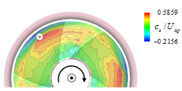
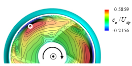
Fig. 2 Time-averaged axial velocity distributions downstream of rotor (ϕ=0.291) |
|
|
|
(a) Overall view |
(b) Around blade tip |
Fig. 3 Trajectory of tip vortex core and absolute vorticity distributions on cross-sections perpendicular to tip vortex |
|
|
|
(a) A-H (Opened region) |
(b) I-M (Ducted region) |
Fig. 4 Distributions of tangential velocity around tip vortex |
|
|
|
(a) θ-z plane |
(b) r-z plane |
Fig. 5 Trajectory of tip vortex center |
|
|
Fig. 6 Illustration of interaction mechanism between tip vortex and shroud wall |
|
|
Fig. 7 Tip vortex core radius |
Fig. 8 Tip vortex circulation |
|
Fig. 9 Distributions of static pressure coefficient along tip vortex |
|
|
(a) Overall view |
(b) Around blade tip |
Fig. 10 Distributions of velocity component along tip vortex axis direction on cross-sections perpendicular to tip vortex |
|
References


