Newsletter 2019.2 Index
Theme : "Mechanical Engineering Congress, 2018 Japan (MECJ-18)"
|
Thrust Vector Control of Transonic and Supersonic Under-Expanded Jets
Toshihiko SHAKOUCHI,
|
Abstract
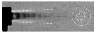
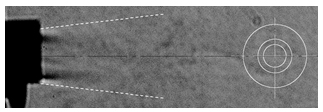
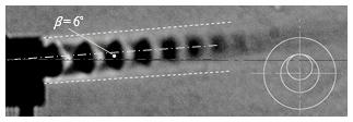
Sub- and supersonic jet flows are used to gain thrust in jet or rocket engine and the thrust vector control is one of the important function. The thrust vector of jet or rocket engine is controlled to change the flying direction by a complex mechanical system usually (1)~(4). In this study, a simple method of thrust vector control of sub- and super-sonic jets by an expanded Coanda nozzle, CC-nozzle, attached to the tip of the pipe nozzle, Pi-nozzle (Fig.1(a), supplied air pressure: P0 = 0.38 MPa) is shown. The inlet diameter, 6.0 mm, of the CC-nozzle is larger than the Pi-nozzle of 3.7 mm, and shifting CC-nozzle in the radius direction to be zero offset distance (Fig.1(b), A-side, Eccentric nozzle array) the jet from Pi-nozzle deflects and attaches to the wall of CC-nozzle by Coanda effect (Fig.2(c), Deflection jet, deflection angle: β = 6˚). In the concentric array (Fig.1(a)), there was so-called bi-stable state in which the jet from the Pi-nozzle flowed straight (Fig.2(a), Straight jet) and enlarged throughout the CC-nozzle (Fig.2(b), Expansion jet). The jet centerline velocity uc issued from
Pi-nozzle gradually decreases after repeating decrease and increase following flow expansion and compression (Fig.3), and the St-jet is smaller than the Pi-jet because of the flow resistance of the CC-nozzle. uc of the Exp-jet is much smaller than the others (Figs.3,4). The thrust F was calculated approximately by the velocity distribution, u (Fig.4), just after the nozzle exit. The thrust of the Deflection jet is the maximum and it is about 1.4 times of the Straight jet. In this study, a simple thrust vectoring method of supersonic jet by shifting the Coanda nozzle was shown. Now, a fluidic thrust vectoring without moving parts is under consideration.
Key words
Sub- and super-sonic jets, Under-expanded jet, Vector control, Thrust, Coanda effect
Figures
| (a) Concentric arrangement | (b) Eccentric arrangement |
| Fig.1 Arrangement of Pipe and Coanda nozzles | |
 |
 |
| (a) Straight jet (concentric nozzle array) | (b) Expansion jet (concentric nozzle array) |
 |
|
| (c) Deflection jet (eccentric nozzle array, β =6˚) | |
| Fig.2 Visualized flow pattern by Schlieren image (α=10°, P0=0.380[MPa]) There are expansion and compression shock waves in the flow pattern. |
|
 |
 |
| Fig.3 Centerline velocity distribution, uc (α =10˚, P0= 0.380 MPa) |
Fig.4 Velocity distribution at the cross section (CC-nozzle, α =10°, P0= 0.380 MPa) |

Fig.5 Total thrust at the nozzle exit ( x =17 [mm])


