Newsletter 2024.11 Index
Theme : "Mechanical Engineering Congress, 2024 Japan (MECJ-24)"
|
Performance Evaluation of Thrust Increasing Guide for Drone
 |
| Atsushi KASE University of Toyama |
Abstract
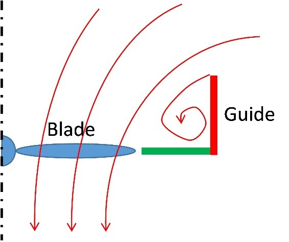
Increasing drone payload and fuel efficiency can be achieved by increasing thrust in a way that consumes less energy. To increase the thrust of drone rotor, attaching the guide with a simple shape was suggested. The guide consists of a cylindrical side plate and an annulus bottom plate (Fig.1). Part of the airflow into the rotating plane is separated at the side plate (Fig.2). This causes negative pressure on the upper face of the bottom plate and generates a pressure difference between the two faces of the bottom plate. The force from this pressure difference acts as an additional thrust, increasing the total thrust of the unit. Because the guide has a simple shape with a small number of parts, it can be designed and manufactured at low costs. In addition, simply attaching the guide externally improves the performance of the current drone easily. The guide has been patented.
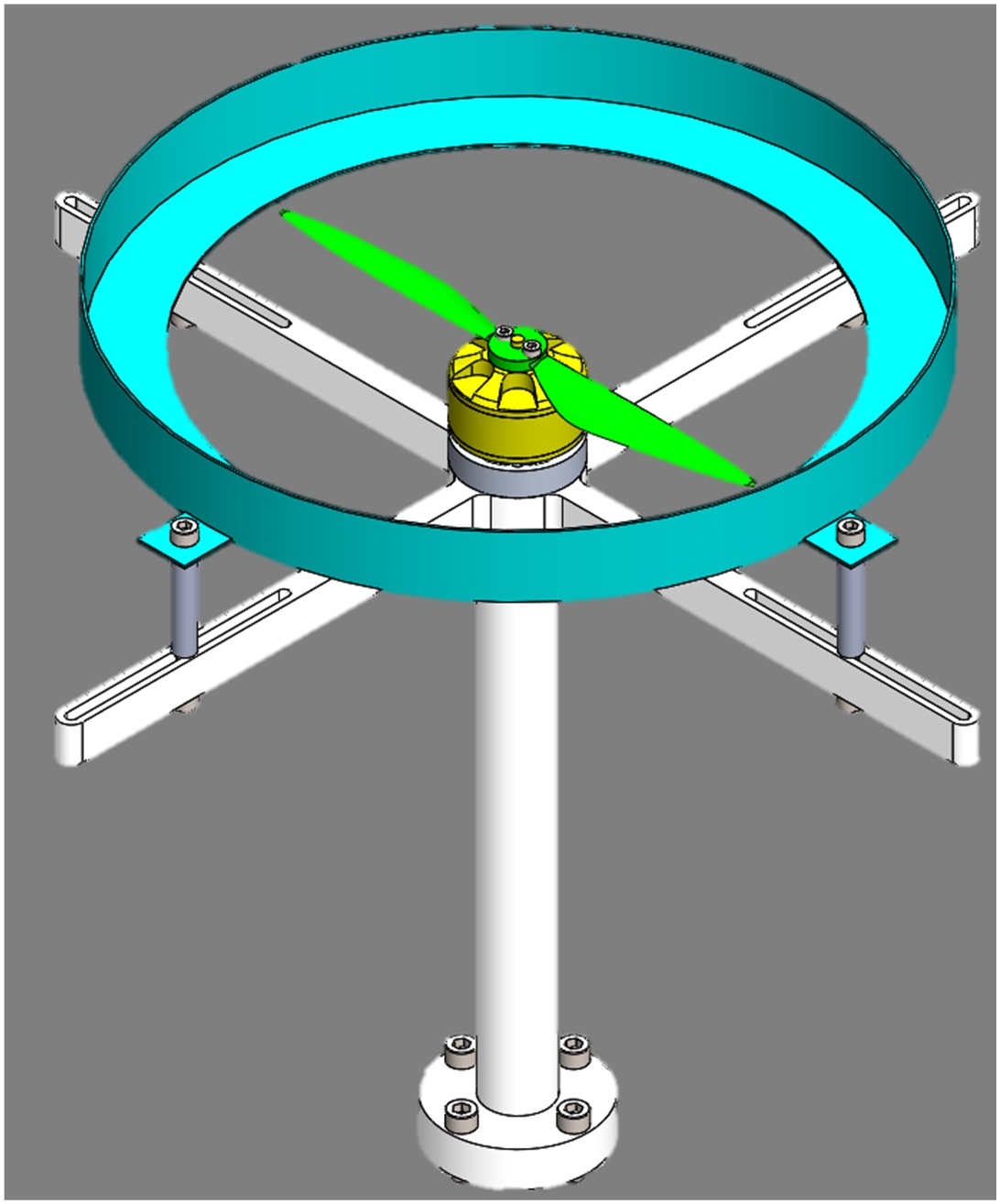
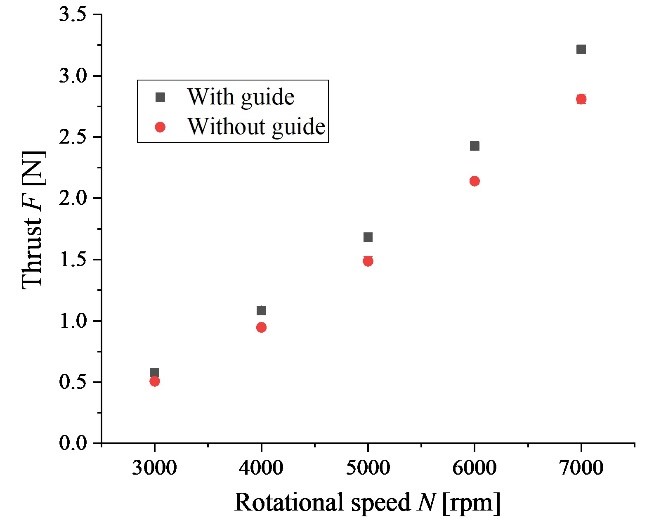
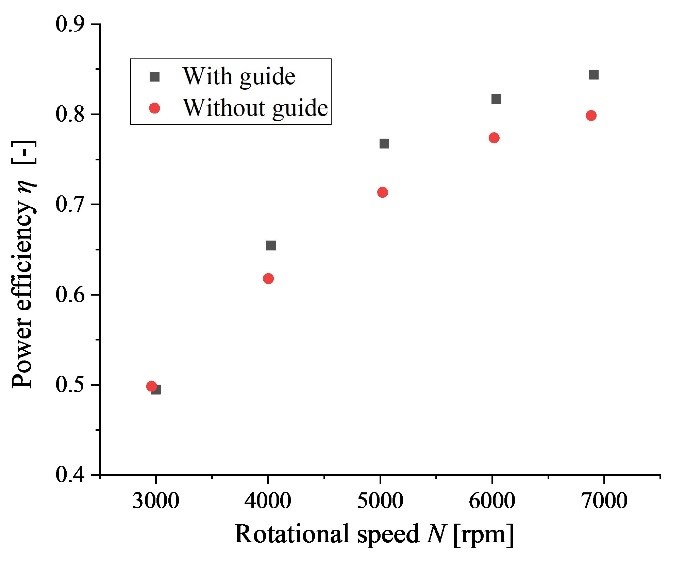
To demonstrate the guide’s performance, a single-rotor test unit (Fig.3) was fabricated using a commercially available wing and motor for drones, and changes in performance with and without a guide were measured. The rotational speed of the rotor was set by PWM control using an Arduino. The thrust and torque generated by the test unit were measured with a 6-axis force sensor and the rotational speed was measured with a non-contact tachometer. Power consumption was also measured using an ammeter and a voltmeter. As a result, it revealed the following. By attaching the guide, the total thrust force was increased at any rotational speed while the total torque around the axis of rotation did not change much (Fig.4). Attaching the guide improved the power and hovering efficiency (Fig.5).
Key words
Unmanned Aerial Vehicle (UAV), Drone, Rotor, Thrust, Efficiency
Figures

Fig. 1 Schematic of the guide.
 |
 |
| (a) Without guide | (b) With Guide |
| Fig. 2 Flow into the rotational plane of the blade. | |
 |
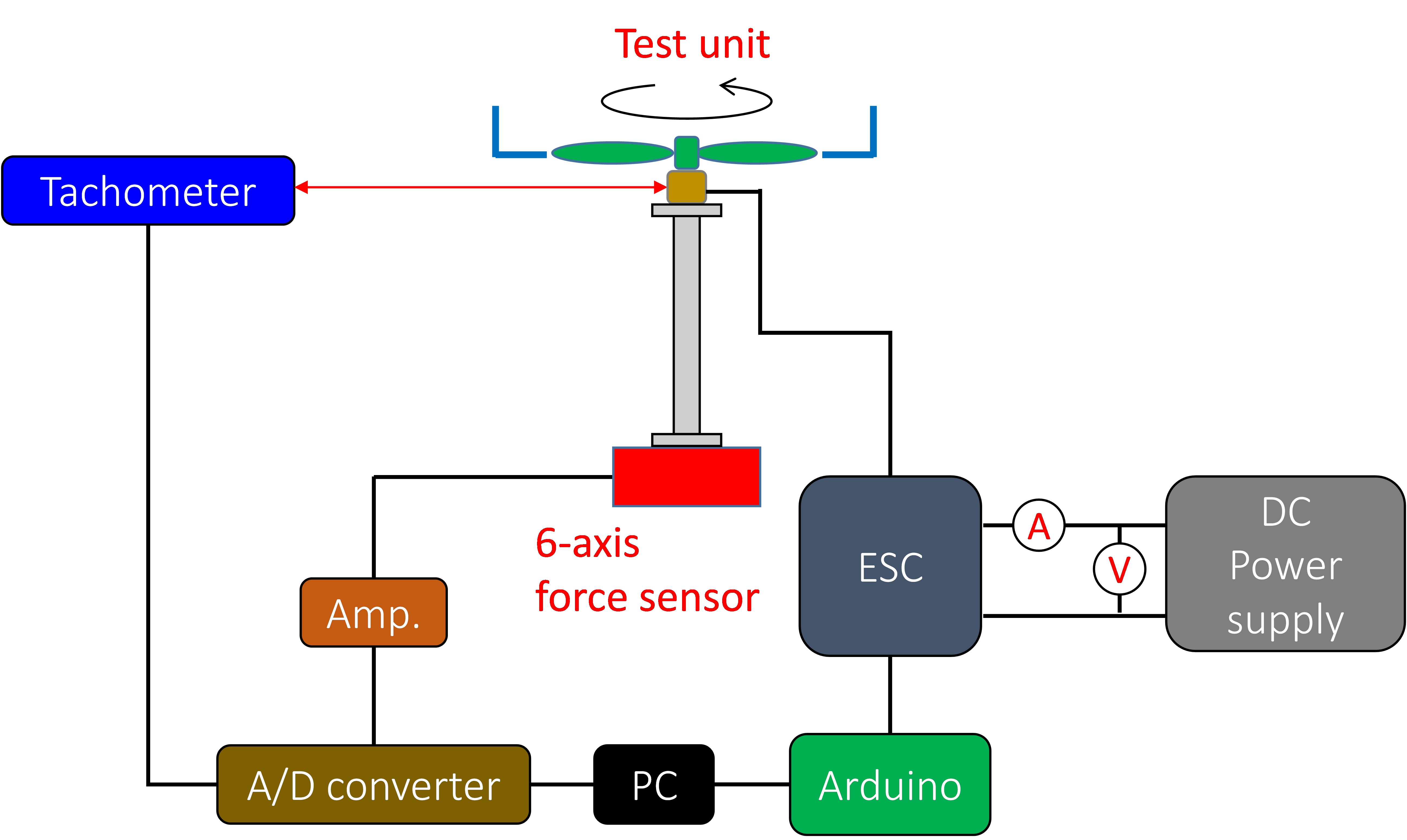 |
| (a) Test unit | (b) Device configuration |
| Fig.3 Experimental setup. | |
 |
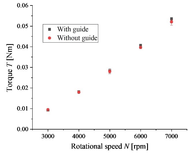 |
| (a) Total thrust | (b) Torque around the axis of rotation |
| Fig.4 Variation of total thrust or torque for rotational speed. | |
 |
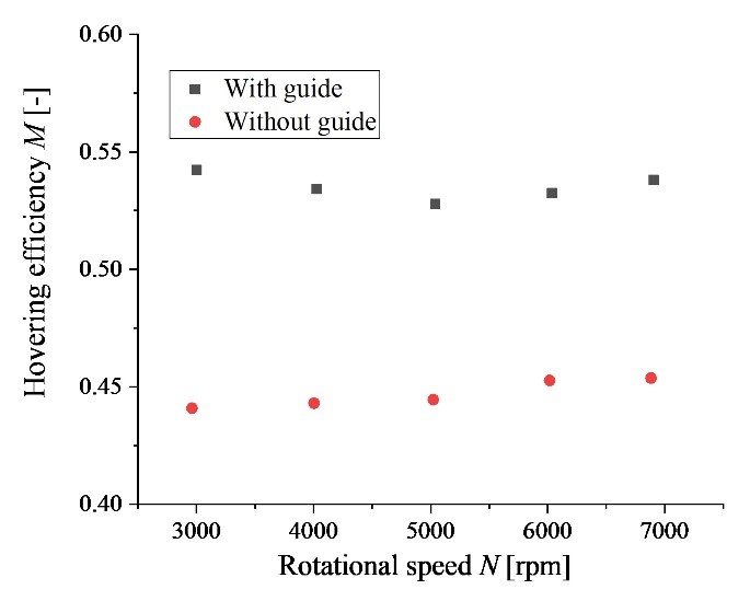 |
| (a) Power efficiency | (b) Hovering efficiency |
| Fig.5 Variation of power efficiency or hovering efficiency for rotational speed. | |

