Newsletter 2024.11 Index
Theme : "Mechanical Engineering Congress, 2024 Japan (MECJ-24)"
|
PIV Measurement of Mini Centrifugal Pump
 |
| Toru SHIGEMITSU Tokushima University |
Abstract
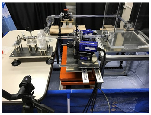
The flow conditions near the casing tongue have a significant impact on the performance and stable operation of the centrifugal pump, so the internal flow conditions have been measured by the experiment and PIV measurement. The internal flow conditions of mini centrifugal pumps especially those smaller than 100mm are less measured by PIV measurement and its flow conditions near the casing tongue are not clarified yet. Therefore, the PIV measurement was conducted near the casing tongue for the mini centrifugal pump having 55mm impeller diameter. The two-dimensional open impellers with different blade outlet angles were selected as the test impellers as shown in Fig.1. The test section and the picture of the PIV measurement instrument are shown in Fig.2 and Fig.3 respectively. FlowMaster Stereo-PIV by LaVision was used for the PIV measurement and the whole test section was made of the acrylic resin including the test impellers. Two CCD cameras with its resolution 2048×2048 pixels were used, and the velocity vector and its contour were calculated by the PIV measurement software DaVis(Lavision). The internal flow conditions near the casing tongue were focused in this research and the PIV measurements of two impellers 22.5 model with blade outlet angle 22.5° and 60 model with blade outlet angle 60° were conducted at different flow rates. The velocity vectors and contour obtained by the measurement is shown in Fig.4. The stagnation point at the casing tongue is related to the flow rates and it is confirmed for both 22.5 model and 60 model. Fig.5 shows the non-dimensional vorticity obtained from the PIV measurement. The strong interaction between the flow from the trailing edge and the casing tongue occurs for 60 model because of the large blade outlet angle. The internal flow conditions of the mini centrifugal pump with 55mm impeller diameter are clarified in detail by the PIV measurement.
Key words
Centrifugal Pump, PIV, Internal Flow
Figures

Fig.1 Test impeller

Fig.2 Test section for PIV

Fig.3 Picture of PIV measurement instrument

Fig. 4 Velocity vectors overlapped with the velocity contours

Fig. 5 Non-dimensional vorticity distribution

