Newsletter 2017.2 Index
Theme : "The Conference of Fluid Engineering Division"
|
Flow Structure of Hub-Corner Separation in a Stator Cascade of a Multi-Stage Transonic Axial Compressor
Seishiro SAITO
|
Abstract
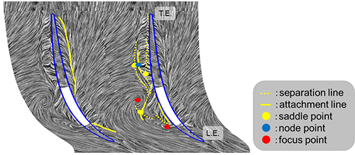
In this study, the hub corner separation in a multi-stage transonic axial compressor has been investigated using a large-scale detached eddy simulation (DES) with about 4.5 hundred million computational cells. The complicated flow field near the hub wall in a stator with partial tip clearances was analyzed by data mining techniques extracting important flow phenomena from the DES results. The data mining techniques applied in the present study include vortex identification based on the critical point theory and topology data analysis of the limiting streamline pattern visualized by the line integral convolution (LIC) method. The analysis result shows that hub-corner separation occurs in the first stator. Because of the rotor-stator interaction, the hub corner separation vortex violently fluctuates with time. It is found from the time-averaged flow field in the first stator that the hub-corner separation vortex formed near the solid part of the stator tip interacts with the tip leakage and secondary flows on the hub wall, resulting in a complicated vertical flow field. Near the leading edge of the stator, the leakage flow from the front partial clearance generates the tip leakage vortex, which produces loss from the leading edge to 10 percent chord position. At the mid-chord, the hub-corner separation vortex suffers a breakdown, resulting in the widespread huge loss production. It is shown from limiting streamlines on the suction surface of the stator that a reverse flow region expands radially from the solid part of the stator tip toward the downstream. From mid-chord position to the trailing edge of the stator, the leakage flow through the rear partial clearance interacts with the secondary flow on the hub wall. The leakage vortex generated along the rear partial clearance becomes major loss factor there.
Key words
Transonic Axial Compressor, DES, Visual Data Mining, Blade Tip Clearance, Hub Corner Separation
Figures

Fig. 1 Computational grid
|
|
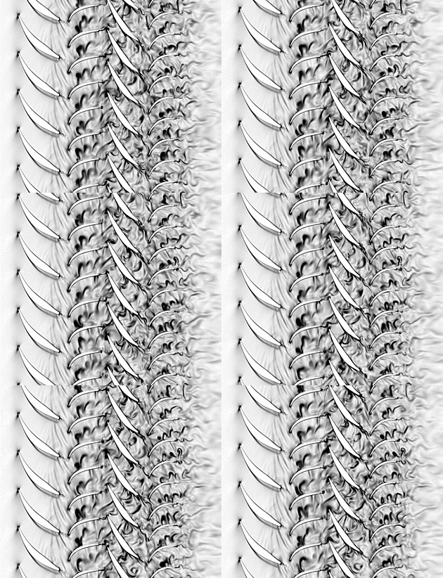
Fig. 2 Magnitude of density gradient at 10%span
 |
 |
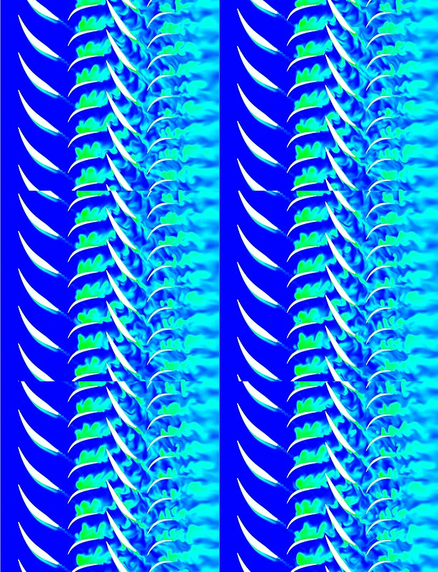
Fig. 3 Entropy at 10%span
 |
 |
| (a) Instantaneous flow structures | (b) Time-averaged flow structures |
| Fig. 4 Limiting streamlines on suction surface and vortex cores in the 1st stator | |

Fig. 5 Limiting streamlines on hub surface (in time-averaged case)


